Tuesday, December 29, 2009

PoE and PoE+(802.3at)

Since the original introduction of PoE, the IEEE has initiated a new project called 802.3at which is commonly referred to as PoE+. This project enhances PoE in a couple of very important ways. First, it provides up to 30W of power to a Powered Device (PD), 25.5 watts to the device and 4.5 for line loss, and allows this power to also run on cabling designed for 1000BASE-T. Secondly,
it provides a new mechanism for communicating power capability and requirements using the 802.1ab Link Layer Discovery Protocol (LLDP). This protocol addition allows PoE+ switches to deliver power more efficiently and thereby provide power to more devices for a given power supply capacity. The new standard is going to be a superset of the 802.3af because it provides all
the same functionality, and more. The table below shows the capabilities of 802.3af versus 802.3at.

In order for 802.3at to provide higher power, Class D (Cat5e) or better cables are required. 802.3at also increases the minimum output voltage of the Power Source Equipment (PSE) from 44 volts to 50 volts. For this reason, you may note that ProCurve PoE+ devices use a 54 volt power supply.

Note:
The detection and classification functions ensure that if two PoE sources are attached together, power will not be improperly applied.
Here are some reasons why you might want to do this:

■ Simplifies installation and saves space - only one set of wires to bring to your appliance.
■ Saves time and money - there is no need to pay for additional electrical power runs or to delay your installation schedule to make them.
■ Minimal disruption to the workplace - the appliance can be easily moved, to wherever you can lay a LAN cable.
■ Safer - no AC voltages need to be added for additional network devices.
■ As well as the data transfer to and from the appliance, you can use SNMP network management infrastructure to monitor and control the appliances.
■ Appliances can be shut down or reset remotely - no need for a reset button or power switch.
■ When implementing wireless LAN systems it simplifies the radio frequency (RF) survey task, as the access point can easily be moved and wired in.

Power Through the Cable:

A standard CAT5 Ethernet cable has four twisted pairs. Only two of these pairs are used for 10Base-T and 100Base-TX data; all four are used for 1000Base-T data. The specification allows two options for using these cables for power:
■ The spare pairs are used. The pair on pins 4 and 5 are connected together and form the positive supply, and the pair on pins 7 and 8 are connected and form the negative supply.
■ The data pairs are used. Since Ethernet pairs are transformer coupled at each end, it is possible to apply DC power to the center tap of the isolation transformer without upsetting the data transfer. In this mode of operation the pair on pins 1 and 2 and the pair on pins 3 and 6 can be of either polarity.


The 802.3af standard does not allow both pairs (spare and data) to be used - a choice must be made. The Power Sourcing Equipment (PSE) applies power to either set of wires. HP ProCurve Networking switches, as a PSE, supply PoE power over the “data pair” or, pins 1 and 2, and the pair on pins 3 and 6. The Powered Device (PD) must be able to accept power from both options
because mid-span equipment must (according to the specification) supply power over the “spare pair” or pins 4 and 5, and the pair on pins 7 and 8.

An obvious requirement of the specification is to prevent damage to existing Ethernet equipment. A discovery process, run from the PSE, examines the Ethernet cables, looking for devices that comply with the specification. It does this by applying a small current-limited voltage to the cable and checks for the presence of a 25k ohm resistor in the remote device. Only if the resistor is present, will the full wattage be applied, but this is still current-limited to
prevent damage to cables and equipment in fault conditions.Once discovered, a different voltage is applied, and based upon the current drawn, the class of device can be determined. This indicates how much power is to be drawn. The 802.3at standard provides both a physical classification and a logical classification, which is even more precise. The PD must continue to draw a minimum current. If it does not (for example, when the device is unplugged) then the PSE removes the power and the discovery process begins again.

General Considerations
The following is an example list of considerations during the planning phase no matter which series of switches are being installed:
■ How many devices need PoE power?
■ What devices will need PoE power?
■ How much power will each device require, in watts?
■ What is the total of all their wattages?
■ Will the devices be connected to a 2910al, 3500yl, 5400 or to a 8200zl
switch?
■ How many ports are needed?
■ How many ports are available?
■ Are the devices to be powered by PoE power supported?

Disclaimer: http://cdn.procurve.com/training/Manuals/PoEPlannngGuide-Oct2009-59918574.pdf
Thursday, December 17, 2009

iACLs; A Service Providers Best Practice on your LAN

When I first started working on Cisco gear back in the early 18th century, ACLs were one the the biggest deployment problems I ran into on a day to day basis. On my first day of being introduced to ACL's was also my first day of introducing our user base to self inflicted Goober Admin Denial of Service attacks (GADOS).... Oh sure they made sense on the various certification exams and talking about them with other geeks over a Bawls Cola at Star Trek conventions. Hey it's just basic boolean logic right? If this variable AND that condition AND this direction MATCH=1 please proceed with instruction, if not drop into the bit bucket. And no I never fell for the old noob; "Time to empty the bit bucket" trick...more then once. But something happened between paper and practice that made me loathe ACL's more then a middle seat and vegetarian airline meal. Is it just me or do vegetarians have the worst farts ever?

anyway...

Any field engineer worth their salt knows that you have to know ACLs like you know where all the speed traps are on your way to work. It is true that you will certainly use them often but ACL theory enables a lot of other features like Flexible Packet Matching, QoS, MCQ, etc... As Yoda would say, Know them you must yes...hmmmm" I really learned ACL practical implementation by fire as a consultant for a major ISP. We used ACL's to the most minute level. As the security threats changed, large hard to follow ACL's had to change. They were eating up too much router resources, folks were afraid to edit them due to a possible outage and staff turnover not only meant the loss of a team member but a loss of the verbal history to understand why many configs were done they way they were.

The iACL came out of that casting forge. ACLs as a feature will not change because of their boolean logic they will only keep expanding to include more AND conditions and some OR conditions. And lets face it, the security threat is not going to get easier only more detailed. A new way of using ACLs was needed at the ISP level. iACLs are not a new feature or a product from Apple they are a new method to use ACL's at your Internet Edge. The "i" in iACL stands for Infrastructure. These entries are very detailed and very powerful. I was going to put in some pointless quote about power and the darkside of the Force but I have already quoted Star Wars once in this blog and that is the legal limit. So let's build out an iACL for my network here in the CodeCave(tm). My network internal address in 172.16.1.0 which is the same I am using on the Internet which is of course illegal which means I am of course lying for simplicity sakes!

Step 00x01: iACLs are as personal to your network as your own underwear is to you. With that is mind, most of us have a good idea what traffic is on the network and if not if you have a feature like NBAR and/or NetFlow this will help shape your initial ACL. To get started, lets build out a Discovery ACL to see what traffic we actually have. I would start out with this one:

access-list 222 permit tcp any any eq 22 log
access-list 222 permit udp any any eq syslog log
access-list 222 permit udp any any eq ntp log
access-list 222 permit ospf any any log
access-list 222 permit icmp any any log
access-list 222 permit tcp any any eq tacacs log
access-list 222 permit ip any any log

Place this ACL on the inbound interface. Remember this eats up router resources so leave this on only as long as you need it to get a good picture of your network. I normally do 3-5 days, however, your mileage may vary! Many things depend on this, number of connections, router size, etc.

Step 00x02:Now I monitor my logs to see what is hitting where. I can do this with the command:

TechWiseTVRTR#sh access-list 222

10 permit tcp any any log (55 matches)
20 permit udp any any eq syslog log (8 matches
..... you get the idea here.....but one more just for fun
70 permit ip any any log (73 matches)

What I am looking for is a small number of hits on my IP ANY ANY statement. A large number means I have stuff not being classified and I need to redefine my Discovery ACL just a bit or dig back into NBAR/NetFlow to see what is flowing thru this network and try again. Remove the Discovery ACL when I am finished.

Step 00x03:Test time! Time for the rubber to hit the road! This is the final step before we create the iACL. I will create a phone call ACL that is very specific. I know this ACL works if the phone in the support center does not ring...

access-list 222 permit ospf host 172.16.1.1 host 224.0.0.5
access-list 222 permit ospf host 172.16.1.1 host 224.0.0.6
access-list 222 permit icmp host 172.16.1.1 192.168.0.0 0.0.255.255
access-list 222 permit tcp host 172.16.1.1 eq 22 192.168.0.0 0.0.255.255
..... You get the idea...OK one more, but this is the last time
access-list 222 permit ip any any log

I put the IP ANY ANY at the end with a log statement to still monitor hits. Run this for a week or so then remove it and proceed to the iACL!!!

Step 00x04: This is it. All the training in a Russian barn in Winter, running up the snow covered hill...Oh sorry, I really need to turn the TV off. Built out the iACL. An iACL has four modules that make it up:

- Deny Special Use and Fragments
- Explicit Permit
- Explicit Deny to Protect the Infrastructure
- Expect Permit for Transit Traffic

Before we get started building out our iACL remember the two most coveted rules in network engineering:

- Never have a end user troubleshoot a network
- Always build out your networks for the next person that follows you.

PLEASE remember to comment out your ACL's, so your history does not leave when you do.

Module 01: Deny Special Use. This module of my iACL looks like this with dated comments:

!---- Module 1 iACL Dec09 Deny Special Use RFC 3330

access-list 222 deny ip host 0.0.0.0 any
access-list 222 deny ip host 127.0.0.0 0.255.255.255 any
access-list 222 deny ip host 192.0.2.0 0.0.0.255 any
access-list 222 deny ip host 224.0.0.0 31.255.255.255 any

***shortened for blog. Check out the table in RFC 3330 for more address***

!--- Module 1 Dec09 Deny RFC 1918 IP space

access-list 222 deny ip 10.0.0.0 0.255.255.255 any
access-list 222 deny ip 172.16.0.0 0.15.255.255 any
access-list 222 deny ip 192.168.0.0 0.0.255.255 any

Module Two:Explicit Permit This is where I allow only authorized external traffic to access internal devices. In this example I will allow routing protocols and SSH only. Basically, it is my control and management traffic.

!---- Module 2 iACL Dec09 Explict Permit

access-list 222 permit ospf host 172.16.1.1 host 172.16.1.2 eq ospf
access-list 222 permit ospf host 172.16.1.1 eq ospf host 172.16.1.2
access-list 222 permit ospf host ospf_neighbor host 224.0.0.5
access-list 222 permit ospf host ospf_neighbor host 224.0.0.6
access-list 222 permit tcp host 172.16.1.4 host 172.16.1.8 eq 22

Module Three: Explicit Deny to Protect the Infrastructure from external sources

!--- Module 3 iACL Dec09 Explicit Deny to Protect Infra
access-list 222 deny ip any 172.16.1.0 0.0.0.255

Module Four: Explicit Permit. This is my transit statement to let internal traffic move about.

!--- Module 4 iACL Dec09 Explict Permit for LAN traffic

access-list 222 permit ip any any

Now you may have noticed that I do not have the source address in many iACL entries. This is becuse I have IP Source Guard enabled at the edge ports and I am enforcing this validation there. This keeps my iACLs smaller and router processing more streamlined. More info in iACL can be found at http://www.cisco.com/go/safe This iACL example is for an Internet Edge router. You can also have a smaller iACL for the LAN as well. Give iACLs a try in your shake and bake lab. They may look a little tough, but it's kinda like eating crap food, breaking it down to smaller parts makes it much easier and that's the idea of modules!

Jimmy Ray Purser

Trivia File Transfer Protocol
Astronomers have long used the Light Year as a standard of measurement. Not to be left out Nuclear Physicists need a measurement standard as well but for much smaller distances. They use the beard second. Which is basically how fast an average (define that I dare you) Nuclear Physicists beard grows in one second, around 5 nanometers. Type in beard-second in Google to see it covert an inch into a beard second to see how small of a measure this really is.

Disclaimer: The article is originally written By JimmyRay, www.networkworld.com

Audio Codec Negotation

Cisco routers acting as voice gateways perform an important job in Unified Communications (UC) deployments. Digital signal processors (DSP) in voice gateways translate voice over IP real-time protocol (RTP) media to time division multiplexing (TDM) required for traditional telephony interoperability. A variety of audio codecs that have different audio quality and bandwidth requirements are used on the voice over IP (VoIP) call leg that determine call quality. Voip dial peers in Cisco routers default to the compressed G.729 audio codec, but codecs can be negotiated in SIP and H.323 gateways. MGCP gateways do not support any codec negotiation because Cisco Unified Communications Manager (CUCM) dictates the codec to the calling party as a result of the region configuration.

H.323 uses the H.245 protocol to provide audio, video, and data media negotiation. SIP leverages session description protocol (SDP) to provide the same information. Regardless of the protocol utilized, the configuration is the same in Cisco IOS of the gateway router. The router 1 voice class configuration below is applied to dial peer 900 with the will send out a listing of prioritized codec capabilities to 10.1.1.1.

ROUTER1:

Voice class codec 90
Codec preference 1 g729a
Codec preference 2 ilbc
Codec preference 3 g722
Codec preference 4 g711ulaw
!
Dial-peer voice 900 voip
Destination-pattern 15…
Voice-class codec 90
Session target ipv4:10.1.1.1

The receiving device will make the final codec determination via the local voice class codec negotiation. If a call is routed from router 1 to router 2, the voice class below will result in an audio codec of g711ulaw because both routers support the codec and it is the called party’s preferred audio codec.

ROUTER2:

Voice class codec 914
Codec preference 1 g711ulaw
Codec preference 2 ilbc
Codec preference 3 g722
Codec preference 4 g729a
!
Dial-peer voice 500 voip
Incoming called-number 15…
Voice-class codec 914

The following debugs can be used to verify the media negotiation in H.323 and SIP respectively. Update your resume before running debugs in production environments.

Debug h245 asn1
Debug ccsip messages


Disclaimer: the article is originally written By Dennis Hartmann, www.networkworld.com

10GE and Network Oversubscription Ratios

Lately I have seen many data center designs that contain 10 Gigabit Ethernet links at the access, distribution and the core hierarchy layers. Traditionally, the bandwidth increases as you reach the core of the network. Historically, networks were like trees. The access network "leaves" are smaller, the distribution network "branches" are a little bigger, and the core network "trunk" is thick. However, due to the prolific use of 10 GE interfaces traditional network design oversubscription ratios are not achievable.

When constructing a multi-tiered network design it is important to consider the bandwidth oversubscription ratios at every layer of the Ethernet switching hierarchy. The idea is that the upstream bandwidth at each layer of the hierarchy must provide adequate bandwidth for those downstream devices. However, statistics drive the ratios that make the total size of the uplink not need to sum to the total amount of the downstream links. This "oversubscription" ratio of downlinks to uplinks is what needs to be closely monitored so that at places in the network bottlenecks do not form that could be difficult to detect and provide poor network connectivity for downstream devices.

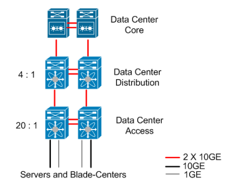
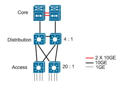
Common access-downlink to access-uplink ratios are 20:1 and distribution-downlinks to distribution-uplink ratios are 4:1. Below is a figure that illustrates this concept. This diagram below shows a 20:1 ratio between access-ports on an Intermediate Distribution Frame (IDF) switch and the uplinks to the distribution switch as well as a 4:1 ratio of distribution switch downlinks to its core uplinks. Traditionally, single Gigabit Ethernet links are used to connect servers, the uplinks are 10GE links, and the core is connected with four 10GE links.

Google

A similar diagram can be found in the Cisco Enterprise QoS Solution Reference Network Design Guide (SRND) version 3.3.

Many newer servers and blade centers are coming with 10GE interfaces. The links between core devices are also using 10GE interfaces. Now we have a design where the leaves are as thick as the trunk of the tree. Therefore, 10GE is changing oversubscription ratios commonly used in network designs.

For example, if an IDF has 240 ports (5 switch stacks of 48 port 10/100/1000Mbps switches) then the total downstream bandwidth is 240Gbps. Therefore, the uplink bandwidth should be 1:20 of 240Gbps or 12Gbps. Those uplinks will probably be a pair of 10GE links. Then consider a set of distribution switches that support only four of those IDFs. Therefore, the total distribution layer downstream bandwidth would be 960Gbps. The uplink bandwidth should be 1:4 of 960Gbps or 240Gbps. However, since we lack the ability to deploy that amount of bandwidth then we are faced with probably using a set of four 10GE links from each distribution switch to each of the pair of core switches.

The second example is when we have servers with 10GE links. Let's say a Nexus switch has 32 10GE links to servers, clusters, and blade centers in the data center. The 20:1 rule would indicate that there would be 16Gbps of uplink bandwidth. That could be satisfied with a couple of 10GE uplinks to the distribution switches. Those distribution switches could only have a couple of these IDF switches downstream in order to require only a few 10GE uplinks to the core switches.

Google

The distribution layer is getting squeezed out with the extensive use of 10GE interfaces within data centers and more organizations may be looking at a 2-tier model rather than the traditional 3-tier model. In the two-tier model, the only ratio used is the 20:1 from the access downlinks to the access uplinks to the core.

40GE and 100GE on the Horizon:

This oversubscription ratio problem won't remain like this for long. We can see already see 40 Gbps Ethernet and 100 Gbps Ethernet on the horizon. Earlier this year the NYSE announced plans to deploy 100Gbps Ethernet. Service providers like Qwest are planning early deployments of 100Gbps in their high-performance backbones. In fact, the some of the first 100Gbps links have already been sold. In my opinion, I agree with those who are proponents of skipping 40Gbps Ethernet and going straight to 100Gbps Ethernet. I also feel that 100Gbps Ethernet is going to gain wider industry adoption than OC-768. History has shown that you just can't beat Ethernet for simplicity, performance, and price.

Conclusion:

The use of 10GE interface for access, distribution, and core will cause network architectures that have leafs with the same bandwidth as the tree's trunk. In order to maintain oversubscription ratios the industry is looking toward using 100GE in the years to come. Network World published their "100G Ethernet cheat sheet" a few weeks ago. I encourage you to check out these articles and keep track of how 100Gbps Ethernet will affect how you design networks in 2010.

Scott

Disclaimer: The article is written by By Scott Hogg, www.networkworld.com

Monday, November 30, 2009

Configuring NetFlow (I love this feature)

Credits to the original Author..

CONFIGURING THE ROUTER

First on Cisco box enable Cisco Express Forwarding:

router(config)# ip cef
router(config)# ip cef distributed

and turn on flow accounting for each input interface with the interface command:

interface FastEthernet3
ip route-cache flow

interface Serial3/1
ip route-cache flow

...

Now, verify that the router (or switch) is generating flow stats. Try command 'show ip cache flow'. Note that for routers with distributed switching (GSR's, 75XX's) the RP cli will only show flows that made it up to the RP. To see flows on the individual linecards use the 'attach' or 'if-con' command and issue the 'sh ip ca fl' on each LC.

IP packet size distribution (36242M total packets):
1-32 64 96 128 160 192 224 256 288 320 352 384 416 448 480
.002 .340 .084 .021 .020 .012 .009 .009 .008 .007 .006 .007 .004 .003 .004

512 544 576 1024 1536 2048 2560 3072 3584 4096 4608
.002 .004 .035 .077 .338 .000 .000 .000 .000 .000 .000

IP Flow Switching Cache, 4456704 bytes
4139 active, 61397 inactive, 712344771 added
871670181 ager polls, 0 flow alloc failures
last clearing of statistics never
Protocol Total Flows Packets Bytes Packets Active(Sec) Idle(Sec)
-------- Flows /Sec /Flow /Pkt /Sec /Flow /Flow
TCP-Telnet 1572735 0.3 58 127 21.4 27.0 14.8
TCP-FTP 6193502 1.4 24 746 35.3 3.6 9.0
TCP-FTPD 1458042 0.3 1534 833 520.9 42.4 4.2
TCP-WWW 93403998 21.7 19 633 432.9 4.9 6.3
TCP-SMTP 16123540 3.7 15 431 59.1 3.4 6.4
TCP-X 687228 0.1 238 276 38.1 20.8 14.3
TCP-BGP 1116819 0.2 3 45 0.7 5.3 16.0
TCP-NNTP 1455156 0.3 1102 176 373.4 106.1 11.9
TCP-Frag 3244 0.0 4 636 0.0 2.8 16.3
TCP-other 188162587 43.8 118 733 5204.5 11.1 6.9
UDP-DNS 38042100 8.8 3 84 27.3 3.8 16.4
UDP-NTP 18760129 4.3 1 76 5.3 1.3 16.3
UDP-TFTP 665 0.0 4 76 0.0 7.9 16.4
UDP-Frag 13111 0.0 2121 1108 6.4 366.8 13.5
UDP-other 195556237 45.5 35 343 1632.5 5.8 16.3
ICMP 149285440 34.7 2 64 72.9 0.9 16.5
IGMP 15315 0.0 167 32 0.5 1660.6 3.9
IPINIP 15112 0.0 35 52 0.1 275.3 14.2
GRE 127489 0.0 3 109 0.1 16.9 16.1
IP-other 348604 0.0 56 447 4.5 21.5 16.2
Total: 712341053 165.8 50 620 8436.8 6.2 12.2

SrcIf SrcIPaddress DstIf DstIPaddress Pr SrcP DstP Pkts
AT4/0.1 128.146.225.194 AT1/0.2 128.194.203.23 06 0019 2CAF 15
AT2/0.10 129.22.250.148 AT1/0.2 129.2.226.43 06 04BA 1A20 1266
AT2/0.11 130.108.110.48 AT1/0.2 170.140.89.100 06 0923 10A3 436
AT1/0.2 170.140.89.100 AT2/0.11 130.108.110.48 06 10A3 0923 462

! Enable the exports of flows with the global commands
router(config)# ip flow-export version 5 origin-as
router(config)# ip flow-export 10.0.0.2 2000

! Create a loopback interface if one does not exist
!
router(config)# interface Loopback0
ip address 10.0.0.1 255.255.255.255

!
! Configure NetFlow export source address
!
router(config)#ip flow-export source Loopback0

If you have tcpdump installed on or near the host you're using to capture flows, the exports can be verified.

netflow:~# tcpdump -n udp port 2000
tcpdump: listening on eth0
12:11:29.953100 10.0.0.1.1868 > 10.0.0.2.2000: udp 1168
12:11:29.962551 10.0.0.1.1868 > 10.0.0.2.2000: udp 1168
12:11:29.975115 10.0.0.1.1868 > 10.0.0.2.2000: udp 1168
12:11:29.984444 10.0.0.1.1868 > 10.0.0.2.2000: udp 1168
12:11:29.993956 10.0.0.1.1868 > 10.0.0.2.2000: udp 1168
12:11:30.003252 10.0.0.1.1868 > 10.0.0.2.2000: udp 1168
12:11:30.015483 10.0.0.1.1868 > 10.0.0.2.2000: udp 1168
12:11:30.024852 10.0.0.1.1868 > 10.0.0.2.2000: udp 1168
12:11:30.034182 10.0.0.1.1868 > 10.0.0.2.2000: udp 1168
12:11:30.043545 10.0.0.1.1868 > 10.0.0.2.2000: udp 1168
12:11:30.053239 10.0.0.1.1868 > 10.0.0.2.2000: udp 1168

SETTING UP NETFLOW COLLECTOR

After installation of NetFlow Collector, edit file /etc/netflow/nfc.conf In this file you can specify, NetFlow Collector Unit Id, this id must correspond with id created by NetFlow Web tool (see installation of NetFlow Web and installation of mysql database). This id is unique for one computing unit ~ one computer. In one unit can run more collectors (one collector ~ at least one netflow export source / router). Unit ID is under section [Main]. In config file there's another section [Database]. You can specify, database name (default nf), hostname (default localhost), username (default root), password, etc ... If you run all-in-one (NetFlow Collector, NetFlow Web and database in one box, you needn't modify anything in the file /etc/netflow/nfc.conf All other parameters are setup by web interface ...
Now, it is all, you can try run collector by typing

netflow:~#/etc/init.d/nfc start


Now it's good time to check syslog for any errors ...

netflow:~#less /var/log/syslog

Wednesday, November 25, 2009

Auto-MDIX dilemma

Configuring Auto-MDIX on an Interface
"When automatic medium-dependent interface crossover (auto-MDIX) is enabled on an interface, the interface automatically detects the required cable connection type (straight through or crossover) and configures the connection appropriately. When connecting switches without the auto-MDIX feature, you must use straight-through cables to connect to devices such as servers, workstations, or routers and crossover cables to connect to other switches or repeaters. With auto-MDIX enabled, you can use either type of cable to connect to other devices, and the interface automatically corrects for any incorrect cabling. For more information about cabling requirements, see the hardware installation guide.

Auto-MDIX is enabled by default. When you enable auto-MDIX, you must also set the interface speed and duplex to auto so that the feature operates correctly. Auto-MDIX is supported on all 10/100 and 10/100/1000-Mbps interfaces and on 10/100/1000BASE-TX small form-factor pluggable (SFP)-module interfaces. It is not supported on 1000BASE-SX or -LX SFP module interfaces."

So you can use a straight through cable to connect two switches, but you then cannot explicitly set the speed and duplex.

"To be fair, I wasn’t aware of the auto-MDIX needing auto-negotiation issue, BUT whenever you are troubleshooting a problem you want to minimize any deviations from known working configurations to eliminate unnecessary variables. I think that I remember reading that auto-MDIX uses the same protocol as auto-negotiation and that’s why both need to be enabled. I’m not positive about that though."

Assume that “correct cabling” means a cross-over cable and “incorrect cabling” means a straight-through cable.

Local Side Auto-MDIX Remote Side Auto-MDIX With Correct Cabling With Incorrect Cabling
On On Link up Link up
On Off Link up Link up
Off On Link up Link up
Off Off Link up Link down

You can refer to the table below, but it’s pretty easy to determine if a link will be up or not: at least one side needs to have auto-MDIX enabled along with auto-negotiation of speed and duplex, otherwise the link will be down.

sw1

sw2


MDIX Speed/Duplex MDIX Speed/Duplex Link Status
on auto on auto up
on auto on hard-set up
on auto off auto up
on auto off hard-set up
on hard-set on auto up
on hard-set on hard-set down
on hard-set off auto down
on hard-set off hard-set down
off auto on auto up
off auto on hard-set down
off auto off auto down
off auto off hard-set down
off hard-set on auto up
off hard-set on hard-set down
off hard-set off auto up
off hard-set off hard-set down

This makes sense because you need at least one side to be able to logically switch the pinouts of a straight-through cable to emulate a cross-over cable. Hard-setting the speed or duplex disables the auto-negotiation protocol (which auto-MDIX must utilize as well) which effectively disables auto-MDIX:

Note: The only command that I know of that will show the auto-MDIX state of an interface (other than looking at the running-configuration of the interface) is the rather verbose “show controllers ethernet-controller fax/x phy | include MDIX” command.

Note: The default setting for switch ports is to have auto-MDIX enabled. This is a pretty recent change though. IOS versions prior to 12.2(20)SE will use the default of “no mdix auto”.

“mdix auto” is the default, so it does not show in the running-configuration:
sw2(config)#do sh run int fa0/32
Building configuration…
Current configuration : 34 bytes
!
interface FastEthernet0/32
end

We can verify that auto-MDIX is on for this interface:
sw2(config)#do sh controll eth fa0/32 phy | i MD
Auto-MDIX : On [AdminState=1 Flags=0x00052248]

Let’s hard-set the speed and see what happens to auto-MDIX:
sw2(config)#int fa0/32
sw2(config-if)#speed 100
sw2(config-if)#do sh control eth fa0/32 phy | i MD
Auto-MDIX : Off [AdminState=1 Flags=0x00010A48]

Notice that our configuration does not state that auto-MDIX has been disabled:
sw2(config-if)#do sh run int fa0/32
Building configuration…

Current configuration : 45 bytes
!
interface FastEthernet0/32
speed 100
end

This verifies that hard-setting the speed and/or duplex turns off auto-MDIX for the interface.

Note: I did test to see if DTP was effected by auto-MDIX. It was not. As long as the link was up, DTP could work it’s trunking magic.

So the long and the short of it is: you can use straight-through cables to connect two Cisco switches as long as you are willing to sacrifice the ability to hard-set the speed and/or duplex on both sides of the link.

Surprisingly i tested above commands on a 2950 and a 3550-SMI switches, i could not get any info regarding auto-mdix.

http://www.cisco.com/en/US/docs/switches/lan/catalyst3560/software/release/12.2_25_see/configuration/guide/swint.html

Polycom soundstation2 and Nortel Meridien option 11c

Apparently when Nortel Meridien 11c PBX is hooked with one of the new DLC cards i.e, 16 port or 48 port,the soundstation2
seems to hang up when initializing, there are couple of solutions to this issue;

(1)Download the latest firmware, this step is mandatory, the old firmware has some issues with latest DLC Crads and sound station2 integration.

(2)As per Polycom's recommendations use M2616 Configuration for soundstation2.

(3)Polycom's documentation:
"SoundStation2 Direct Connect is compatible with any digital voice port on NORTEL® Meridian®, Meridian 1 (option 11 to 81), SL-1, or SL-100 PBX with the exception of those supporting MBS (CENTREX®) phone sets. In addition to the basic product functions, it supports two special functions - Conference and Transfer - in the same manner as the default M2616 Model 20, using key number position 3 for Conference and key number position 6 for Transfer. Contact your PBX Administrator to confirm that the Conference and Transfer functions at the port are assigned to these key number positions."

(4)A forum stated the same issue, one of the guy responded'
"I have been in touch with Polycom support (an on-line support system, no TELEPHONE support - how ironic). They have stated that "The SoundStation2 Nortel will emulate a M2009 set if there is no digital telephone set attached to the interface."

(5)You can try this,
"Carl, do you have a 2616 to test with? Start with the basics. See if the port will work with a 2616, if you have one. If you don't have a 2616, plug in a 3903 or 3904 and you should still be able to get dial-tone."

I read on another forum, that there are dip switches you need to set, in order for the unit to work correctly (Not specific to your issue, but I would set them ahead of time).

The separate box where all the cables and power goes turn it upside down, by the Polycom logo on the serial number sticker there will be a tiny square overlay sticker, peel it back and it will reveal 3 jumper switches, from memory turn number 3 off
1 = on
2 = on
3 = off


you can try this if you want to,

Configure your TN 6-12 as a TYPE 3904 (instead of 2616 as they suggest in the user guide), then use the supplied connectors and an M3904 set. Reason I would try this is that as per above printed info, they want you to use an appropriate Nortel phone in line with the unit. Since you don't have a 2616 phone, may be you can get away with M3904. That way the PBX will at least have the correct phone type matched to the TN, and I doubt that the Soundstation will know the difference, as long as your conf / trn keys are as per user guide.

Second thing to try is to configure your TN 6-12 as an TYPE 2009 (this is before my time, so not sure that you can just enter this type), then connect the sound station directly to the voice point, meaning you are then using their suggested method.

References, credit to original authors

Ploycom KB

http://www.polycom.com/support/voice/soundstation/soundstation2.html

PBX-Info

http://www.pbxinfo.com/forums/showthread.php?t=35075

Nortel KB

http://support.nortel.com/go/main.jsp?cscat=DOCUMENTATION&poid=8310&catOID=-9602&viewOptSelect=&viewOpt1=&viewOpt2=DEFAULT&searchText=&searchType=fulltext&x=43&y=3

Monday, October 26, 2009

Difference Between HWIC-2FE and HWIC-4ESW

Cisco EtherSwitch 4- and 9-Port High-Speed WAN Interface Cards

Q. Can the individual ports be configured as routed ports?
A. No, the Cisco EtherSwitch HWICs do not support routed ports. This means you cannot assign an IP address directly to the interface and make it a Layer 3 interface.


Q. Can I assign each switch port to a unique VLAN? If so, are there any limitations?
A. Each switch port can be assigned to its own VLAN, effectively providing four additional routed ports. However, there are serious performance and feature limitations to doing this. The VLAN interfaces are truly Layer 3 switching interfaces and are treated uniquely among interface types on the router. Many features are not supported or tested on these interfaces, including Point-to-Point Protocol over Ethernet (PPPOE) termination, Layer 2 Tunneling Protocol Version 3 (L2TPv3) termination, MAC address assignment, Layer 3 QoS, and others. You should carefully test any desired feature and solution prior to deploying it.

http://www.cisco.com/en/US/prod/collateral/routers/ps5853/prod_qas0900aecd8016c026_ps5854_Products_Q_and_A_Item.html


Cisco 1- and 2-port Fast Ethernet High-Speed

Q. Can these interfaces be used as switch ports?
A. No, these are native Layer 3 interfaces, designed for routing. They can be configured to bridge using the router CPU. There is no switching application-specific integrated circuit (ASIC), nor are switching features supported.

http://www.cisco.com/en/US/prod/collateral/routers/ps5854/prod_qas0900aecd80582015.html


Tuesday, April 21, 2009

Marking using NBAR

Command List

Use the following commands to complete this exercise:

Command

Description

no service-policy {input | output} policy-map-name

Removes a service policy from an input or output interface.

show ip cef

Displays the state of Cisco Express Forwarding (CEF).

ip nbar protocol-discovery

Configures NBAR to discover traffic for all protocols known to NBAR on a particular interface.

clear ip nbar protocol-discovery

Clears NBAR protocol discovery statistics.

show ip nbar protocol-discovery [interface interface-spec]

Displays the statistics gathered by the NBAR protocol discovery feature.

ip access-list {standard | extended} access-list-name

Defines an IP access list by name.

permit tcp source source-wildcard destination destination-wildcard [operator [port]]

Sets conditions to allow a TCP packet to pass a named IP access list.

permit udp source source-wildcard destination destination-wildcard [operator [port]]

Sets conditions to allow a UDP packet to pass a named IP access list.

class-map class-map-name

Creates a class map to be used for matching packets to a specified class.

match protocol protocol-name

Configures the match criteria for a class map on the basis of the specified protocol.

match access-group {access-group | name access-group-name}

Configures the match criteria for a class map on the basis of the specified access list.

policy-map policy-map-name

Creates or modifies a policy map that can be attached to one or more interfaces.

class {class-name | class-default}

Specifies the name of the class whose policy you want to create or change or to specify the default class.

set dscp dscp-value

Marks a packet by setting the differentiated services code point (DSCP).

service-policy {input | output} policy-map-name

Attaches a policy map to an input, or an output interface.

show class-map class-map-name

Displays all class maps and their matching criteria.

show policy-map policy-map

Displays the configuration of all classes for a specified service policy map or all classes for all existing policy maps.

show policy-map interface interface-name [input | output] [class class-map-name]

Displays the packet statistics of all classes that are configured for all service policies on the specified interface.

Table 1: Configuration and monitoring commands used in this Lab exercise

Complete Solution;

ip access-list extended VoIP-RTCP
permit udp any any range 16384 32767
!
ip access-list extended Voice-Control
permit tcp any any eq 1720
permit tcp any any range 11000 11999
permit udp any any eq 2427
permit tcp any any eq 2428
permit tcp any any range 2000 2002
permit udp any any eq 1719
permit udp any any eq 5060
!
class-map match-any real-time

match protocol rtp
match protocol icmp
match access-group name VoIP-RTCP
class-map match-any mission-critical
match protocol sqlnet
match access-group name Voice-Control
class-map match-all interactive
match protocol citrix
class-map match-all bulk
match protocol ftp
class-map match-any scavenger
match protocol kazaa2
match protocol napster
!
policy-map mark-nbar
class real-time
set dscp ef
class mission-critical
set dscp af31
class interactive
set dscp af21
class bulk
set dscp af11
class scavenger
set dscp cs1
class class-default
set dscp default
!
interface fastethernet0/0
service-policy input mark-nbar


----------------------------------------------------------

Configuration 12: Configuration description
Step 18 The following commands need to be entered on R1 router.
R1#show policy-map interface fastethernet0/0
FastEthernet0/0
Service-policy input: mark-nbar
Class-map: real-time (match-any)
5 packets, 570 bytes
5 minute offered rate 0 bps, drop rate 0 bps
Match: protocol rtp
0 packets, 0 bytes
5 minute rate 0 bps
Match: protocol icmp
5 packets, 570 bytes
5 minute rate 0 bps
Match: access-group name VoIP-RTCP
0 packets, 0 bytes
5 minute rate 0 bps
QoS Set
dscp ef
Packets marked 5
Class-map: mission-critical (match-any)
7298 packets, 770942 bytes
5 minute offered rate 27000 bps, drop rate 0 bps
Match: protocol sqlnet
6596 packets, 694955 bytes
5 minute rate 22000 bps
Match: access-group name Voice-Control
702 packets, 75987 bytes
5 minute rate 6000 bps

Tuesday, April 14, 2009

QOS - MQC and class Based Markings Demystified

The 6-bit DSCP field (described in RFC 2474) defines the per-hop behavior (PHB). A PHB is an externally observable
forwarding behavior or QoS treatment performed by a network device such as a router or a switch.

The four different DiffServ PHBs are Best Effort (BE), Class Selector (CS), Assured Forwarding (AF), and Expedited
Forwarding (EF):

n BE is indicated when all 6 bits of the DS field are zero, and it has no specific QoS treatment.
n CS is used for backward compatibility with IP Precedence, and when using this PHB, the last 3 bits of the DSCP
field are zero.
n AF (defined in RFC 2597) specifies four different classes, along with three different drop precedences.
When using AF, the first 3 bits of the DS field define the queuing class (1 to 4), and the last 3 bits define the drop
precedence (the likelihood of the packet being dropped [1 to 3]). AF PHB names are often written in the AFxy
format, where x is the queuing class and y is the drop precedence.
n EF (RFC 3246) specifies a low delay, low jitter, and low packet-loss QoS treatment with a bandwidth guarantee.


Follow the sequence of commands mentioned above to configure class based marking of trafficStep 1 The following commands need to be entered on R1 router.

access-list 101 permit tcp any any eq ftp
access-list 101 permit tcp any any eq ftp-data

Configuration 1: Configuration description

Step 2 The following commands need to be entered on R1 router.
access-list 102 permit tcp any any eq www

Configuration 2: Configuration description


Step 3 The following commands need to be entered on R1 router.
class-map match-ftp
match access-group 101
!
class-map match-www
match access-group 102

Configuration 3:
Configuration description
Step 4 The following commands need to be entered on R1 router.
policy-map mark-apps
class match-ftp
set dscp af11

class match-www
set dscp default

Configuration 4: Configuration description

Step 5 The following commands need to be entered on R1 router.
interface fastethernet0/0
service-policy input mark-apps

Configuration 5: Configuration description

Step 6 Class FTP: matched_ 1749__ marked_ 1749__
Class WWW: matched_ 1028__ marked_ 1028__
Class class-default: matched_ 28733_

Sunday, February 22, 2009

Resetting the Password on a 3560

The below Method is for when password Recovery Mechanism is Enabled For other situations and scenarios see the link below.


Step 0 : Press the Mode button, and at the same time, reconnect the power cord to the switch.

You can release the Mode button a second or two after the LED above port 1 goes off. Several lines of information about the software appear along with instructions:

The system has been interrupted prior to initializing the flash file system. The following
commands will initialize the flash file system, and finish loading the operating system
software#

flash_init
load_helper
boot

Step 1 Initialize the Flash file system:

switch: flash_init

Step 2 If you had set the console port speed to anything other than 9600, it has been reset to that particular speed. Change the emulation software line speed to match that of the switch console port.

Step 3 Load any helper files:

switch: load_helper

Step 4 Display the contents of Flash memory:

switch: dir flash:

The switch file system appears:

Directory of flash:
13  drwx         192   Mar 01 1993 22:30:48  c3560-i5-mz.121.19-EA1
11  -rwx        5825   Mar 01 1993 22:31:59  config.text
18  -rwx         720   Mar 01 1993 02:21:30  vlan.dat

16128000 bytes total (10003456 bytes free)

Step 5 Rename the configuration file to config.text.old.

This file contains the password definition.

switch: rename flash:config.text flash:config.text.old

Step 6 Boot the system:

switch: boot

You are prompted to start the setup program. Enter N at the prompt:

Continue with the configuration dialog? [yes/no]: N

Step 7 At the switch prompt, enter privileged EXEC mode:

Switch> enable

Step 8 Rename the configuration file to its original name:

Switch# rename flash:config.text.old flash:config.text

Step 9 Copy the configuration file into memory:

Switch# copy flash:config.text system:running-config
Source filename [config.text]?
Destination filename [running-config]?

Press Return in response to the confirmation prompts.

The configuration file is now reloaded, and you can change the password.

Step 10 Enter global configuration mode:

Switch# configure terminal

Step 11 Change the password:

Switch (config)# enable secret password

The secret password can be from 1 to 25 alphanumeric characters, can start with a number, is case sensitive, and allows spaces but ignores leading spaces.

Step 12 Return to privileged EXEC mode:

Switch (config)# exit
Switch#

Step 13 Write the running configuration to the startup configuration file:

Switch# copy running-config startup-config
http://www.cisco.com/en/US/docs/switches/lan/catalyst3560/software/
release/12.1_19_ea1/configuration/guide/swtrbl.html#wp1090048

Power and Memory Allocation errors on a 3550

%SYS-2-MALLOCFAIL & %ILPOWER-3-CONTROLLER ERR

I received these two errors today on a 3550 Running CCME

--%ILPOWER-3-CONTROLLER ERR

This Error is due to power spike on an interface most probably from an IP phone, causing the power controller to go down shut and then no shut the interface. proper grounding for the IP phone.

http://supportwiki.cisco.com/ViewWiki/index.php/ILPOWER-3-CONTROLLER_ERR:_Controller_error%2C_Controller_number_(chars):_accessing_failed_error_message_on_a_Catalyst_3550_series_switch

--%SYS-2-MALLOCFAIL

The Error is due to unavailability of the free memory block, a process is trying to write data on for details see.

http://supportwiki.cisco.com/ViewWiki/index.php/The_%22SYS-2-MALLOCFAIL%22_messages_are_displayed_in_the_logs_of_Catalyst_switches

Tuesday, January 13, 2009

Connecting Cisco Switches to Avaya/Polycom/HP and Etc Phones

Only Cisco & Mitel phones will use CDP to discover the Voice VLAN, however other methods exist to inform the IP Phones of the voice VLAN. Ericsson/Aastra, Nortel & Avaya all use DHCP they boot on the access VLAN and via DHCP options discover the Voice VLAN, they then release the IP address and restart using 802.1q tagged frames.
Although the functionality of an Access port configured like this:

CODE

switchport mode access
switchport access vlan 10
switchport voice vlan 100
is the same as a trunk configured like this

CODE

switchport trunk encapsulation dot1q
switchport mode trunk
switchport nonegotiate
switchport trunk native vlan 10
switchport trunk allowed vlan 10,100


There are other implations of hard-coding the port as a trunk which is why I wouldn't recommend it.
I have sucessfully deployed several Nortel, Ericsson & Mitel IP Telephony systems using access ports with voice vlans.

Back to the original problem though... Are you plugging the phones directly into the switch using a fully-wired patch cable (i.e. not via the infrastructure cabling)? Are you trying to hard-code speed & duplex (don't....). Have you done any debugging?


I've always understood from Cisco that non-cisco devices should have a proper .1q trunk configured.

For example:
http://www.cisco.com/en/US/products/hw/switches/ps708/products_configuration_example09186a0080891554.shtml

It doesn't make a huge difference, I suppose, because you end up with something similar in either case.

Like you, I have deployed Nortel, Ericsson and Siemens IP phones using my particular bias when it comes to switch configuration. :)

Not that I've often had power issues. Once I found a switch that was refusing to grant power due to being "out of memory", which was somehow caused by a damaged stackport.

LLDP - now theres a thing. Yes this should work but its only supported on the newer Catalysts (2960, 3560, 3750) and 6500's. For some reason (to sell more product...) Cisco have refused to add LLDP to the older switches. I know Nortel support LLDP as well as the newer Cisco IP Phones. Ericsson/Aastra certainly don't in the latest firmware but its supposed to be coming? Not sure about Mitel or Avaya?


I have some Polycom phones going to an Adtran T1 L3 switch (PoE, basically a Cisco!) that they say can use CDP. The phones are SPIP-500/501


I recall HP switches used CDP until firmware updates in 2005/2006.

Don't forget Cisco supports LLDP, though, if your phones support it.

Avaya does support LLDP. Avaya phones also work with either switchport voice vlan OR 802.1Q trunk ports using DHCP/Text files to configure VLAN assignment.

I have heard, If we add one by one Avaya or Nortel IP Phones to cisco switches (mostly 48 port), SOME TIMES last couple of phone finds not enough power to bootup. This usually happens when all the 48 ports are used.

Courtesy
http://www.tek-tips.com/viewthread.cfm?qid=1517008&page=1

Monday, January 12, 2009

Upgrading from 4.X to CUCM 6.0

I found this brief detail from a forum regarding The upgrade process, latter i will more details. courtesy cukon.


Yes it is possible to upgrade directly from CCM 4.2 to CCM 6.You need to download DMA (data migration assistant) tool from cisco, then you start to run this tool on CCM 4.2 publisher and output of this tool is file with CCM configuration, then you can install CCM 6.x, installation process ask you if you want to make fresh installation or you migrate from old CCM 4.x, you choose second option and installation process will ask you for file from DMA tool (file must be stored on some network directory). After CCM 6 published is installed you must add subscriber on the new CCM web admin and then you can install it...thats all :-)

About licences: licenses are migrated automatically based on number of endpoints in CCM 4 (you can add some virtual phones in CCM 4 before use DMA tool if you want to have more DLU licences in CCM 6 :-) ) to the new CCM6.At the end you must download these "migrated licences" from CCM6 and use it with ordered upgrade PAK from cisco on cisco WEB.Output of this will be true CCM6 licences which you must upload back to CCM6.

Thats all :-) Good for you will be upgrade guide which you can download from cisco pages.

Friday, January 9, 2009

WildCards in CCM 4.1 Demystified

I had Some problems understanding couple of wild cards the following examples have clarified my concepts in detail.

Numbers to Match---------------------------Route Pattern
2200–2299-------------------------------------22XX
2200–2499-----------------------------------2[2–4]XX
2200–2299 and 2400–2699------------2[24–6]XX

1231[^0-2]6[981]+

The above example illustrates only single entry resides in [], so except the range between 0-2 any single digit number can be matched with this entry. [981] means only 9 8 or 1 can occupy this region.

After all the digits are dialed, if the CCM has more than one route pattern that matches all the digits, the CCM uses the most specific route pattern. For example, consider the following scenario:
Dialed number: 555-1234

CCM route pattern matches: 555-12XX, 555-12[2–4]X

In this example, the CCM uses the 555-12[2–4]X route pattern, because 100 potential matches exist for the 555-12XX route pattern whereas only 30 potential matches exist for the 555-12[2–4]X route pattern. Therefore, the 555-12[2–4]X route pattern is deemed to be
more specific.

Monday, January 5, 2009

How to Configure EtherSwitch Modules in 2851-2821 and Changing the 3750 IOS on the EtherSwitch.

In this guide i am going to focus on how to add EtherSwitch modules in cisco 2851 and 2821 and changing the IOS on the EtherSwitch. cisco 2851 can reside a 48 port EtherSwitch module. i am going to describe this step by step.

http://www.cisco.com/en/US/prod/collateral/routers/ps259/product_data_sheet09186a00801aca3e.html

1 - Remove the Steel clamping on the back to insert the module.

2 - Now insert the module and push it gently until you are satisfied the module is completely inside, this step can be a little daunting because initially it took quite a while to set up the module correctly in the slot, The module wont come up if it isn't inserted correctly, it took a number of insertions and removals until the module finally came up so keep trying if you are having difficulties in inserting the module, in the latter releases it took much less time to set up the module. cisco 24 port Etherswitch module took less time to set up i guess beacuse of the special handle provided with the module.

3 - Next step is to access the module.

4 - Go to routers CLI and give an IP address to the GigabitEthernet 1/0 interface (may be diffrernt in your case), if you type #sh ip interface brief you can clearly see one gig interface is seperatly mentioned right at the bottom of the output that is your gig interface i.e your backplane connectivity to the router. assign an IP address to the interface and a #no shut. the backplane interface is UP.

5 - now type #Service-module GigabitEthernet 1/0 session , to access the module once you have accessed you can update the Image on the Switch.

6 - To Update the IOS on the switch start the TFTPD on the PC connected to FastEthernet interface. on the EtherSwitch Module issue the following commands.

7 - make this interface routed port assign an IP address to this interface.

8 - start the TFTPD on the PC.

9 - issue the following commands on the switch CLI.

10 - #copy tftp flash: , give the required IP address and the name of the IOS file the output will show exclamation marks and the copying will start.

11 - #boot system flash:IOS-name.bin to set the new IOS.

12 - #wr er this will not erase the boot system flash command.

13 - To go back to the router CLI press ctrl+shift+6 and then press "x".

14 - #disconnect ,to terminate the session with the router CLI.